


- WEBSITE -


Current location: Home > BLOGS > Technical Documentation >
Cold Roll Forming Equipment: Manufacturing Technology and Production Application
Time:2026-06-26 06:10:45 Author:xiangyi Click:122
Cold Roll Forming Equipment: Manufacturing Technology and Production Application
Cold roll forming equipment represents versatile manufacturing technology that transforms flat metal coils into precisely shaped profiles through continuous, incremental bending operations without heating. The manufacturing of this equipment demands advanced engineering capabilities, precision machining, and rigorous quality control across multiple subsystems. This article examines the production process, technical configuration, and practical applications of cold roll forming equipment in industrial manufacturing environments.
Equipment Manufacturing Process
The manufacturing of cold roll forming equipment begins with detailed engineering design using computer-aided design (CAD) and finite element analysis (FEA) software. Engineers calculate roll profiles using specialized roll forming simulation software that predicts material flow, strain distribution, and springback compensation. The design phase determines machine configuration - number of roll stations, roll shaft diameter, frame structure, drive system specifications, and auxiliary equipment integration based on target profile specifications (material thickness range, yield strength range, profile complexity, production speed requirements).
Frame fabrication constitutes a major manufacturing stage. Manufacturers use heavy steel plates (Q235B or Q345B, thickness 20-60mm) cut by CNC plasma or laser cutting machines according to drawings. Welding procedures follow approved welding procedure specifications (WPS) - submerged arc welding for thick plates, gas metal arc welding (GMAW) for thinner sections. Post-weld heat treatment (stress relief at 600-650°C for 2-3 hours) prevents distortion during subsequent machining. Machining of mounting surfaces employs CNC gantry machining centers or boring-milling machines to achieve flatness tolerance within 0.1mm per meter and hole position accuracy within ±0.05mm. Frame wall thickness ranges from 30mm to 80mm depending on forming load calculations using FEA software.
Roll tooling manufacturing requires highest precision among all components. Roll drawings specify profiles with dimensional tolerances of ±0.02mm. Roll blanks are rough machined from forged alloy steel (typically 42CrMo or 40Cr) then heat treated to achieve hardness of 50-55 HRC. Finish machining uses CNC lathes and CNC milling machines to achieve required profiles. Complex roll profiles may require 5-axis CNC machining centers. Surface grinding achieves surface roughness Ra 0.8μm. Final inspection uses coordinate measuring machines (CMM) or 3D scanners to verify profile accuracy before assembly. For manufacturers producing multiple profile families, roll design may incorporate adjustable features - movable roll blocks or interchangeable roll segments that accommodate different profile dimensions without complete rollset changeover, reducing tooling investment and changeover time.
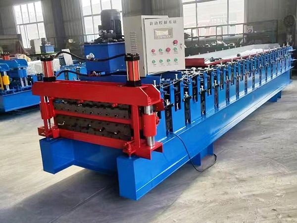
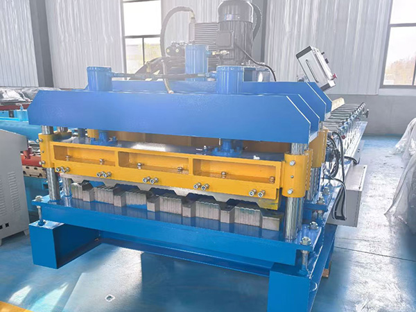
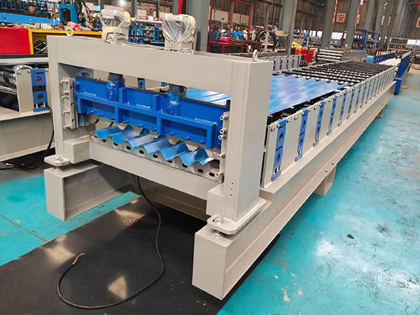
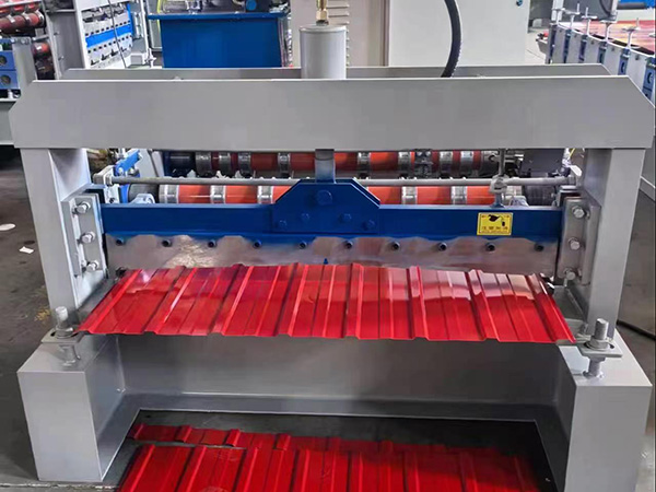
Machine Structure and Drive System
Cold roll forming equipment consists of a rigid frame, multiple roll stations, drive system, and control system. Frame structure adopts either integral welding type or split type connected by tie rods. Integral welding provides higher rigidity but complicates transportation for large machines (width exceeding container internal dimensions of 2350mm). Split type facilitates container shipping but requires precise field assembly and alignment - connection surfaces use precision machined mating surfaces with positioning pins and high-strength bolts (grade 8.8 or 10.9). Frame rigidity calculation uses FEA software to ensure deflection under maximum forming load does not exceed L/1000 (L = roll shaft span) to maintain profile dimensional accuracy.
Roll stations comprise roll shafts, bearing housings, rolls, and adjustment mechanisms. Roll shaft diameter calculation considers bending stress and deflection - typical diameters range from 40mm (small machines for thin materials) to 120mm (heavy-duty machines for thick or high-strength materials). Shaft material is 40Cr or 42CrMo, heat treated to 28-32 HRC for toughness. Bearing selection uses cylindrical roller bearings (for radial load) and thrust bearings or angular contact ball bearings (for axial load from forming forces). Bearing housings bolt to frame side plates, with adjustment slots allowing lateral roll position adjustment (±10mm to ±20mm typical) for profile width variation or roll gap fine-tuning. Roll gap adjustment mechanisms include manual handwheel with lead screw (economic) or motorized adjustment with position feedback (premium), enabling precise gap control and recipe-based automatic adjustment.
Drive system configuration significantly influences machine performance and flexibility. Traditional systems use a main motor with reduction gearbox driving a distribution gearbox that transmits power to each station via transmission shafts and bevel gear pairs. This system provides positive synchronization and cost-effectiveness but generates mechanical losses (approximately 15-20% power loss) and requires periodic gear lubrication and alignment maintenance. Gear material is 20CrMnTi or 42CrMo, heat treated to 58-62 HRC for tooth surfaces. Modern systems employ individual servo motors for each roll station, enabling independent speed control and eliminating transmission losses. Servo-driven systems also allow asymmetric profile forming (like Z sections) where roll speeds differ between upper and lower rolls to compensate for different material flow lengths. Servo motor power calculation considers forming torque requirement at each station - typical powers range from 0.75kW to 5.5kW per station depending on material thickness, yield strength, and roll diameter.
Technical Specifications
Material Thickness Range: 0.3-4.0mm (standard), up to 8.0mm (heavy-duty)
Material Width Range: 50-1800mm (customizable)
Number of Roll Stations: 8-24 stations (profile-dependent)
Roll Shaft Diameter: 40-120mm (material/thickness-dependent)
Forming Speed Range: 0-30 m/min (standard), up to 50 m/min (high-speed)
Main Motor Power: 7.5-75kW (depending on profile complexity and speed)
Drive Type: Gear transmission / Individual servo drives / Mixed (gear + servo)
Roll Material: 42CrMo, heat treated 50-55 HRC, surface chrome plated (optional)
Machine Weight: 3-25 tons (depending on configuration and profile capacity)
Control System: PLC with touchscreen HMI, optional servo drives with closed-loop control
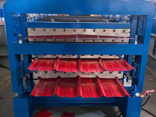
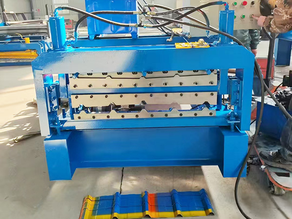
Production Line Integration and Auxiliary Equipment
Cold roll forming equipment rarely operates as standalone equipment - it integrates into production lines with auxiliary equipment to create complete manufacturing systems. A complete line includes decoiler (hydraulic or passive), guiding device (powered or manual), roll forming machine (main forming section), inline processing stations (punching, notching, embossing, etc.), cutoff press (flying cutoff or stationary cutoff), and run-out handling system (conveyor, stacker, bundler). Integration requires mechanical alignment (coaxiality of equipment centers within ±2mm) and electrical synchronization (speed matching between sections, particularly synchronization between roll forming speed and inline processing operations).
Inline punching integration enables continuous production without secondary operations. Punching stations locate after the roll forming section (for holes that must be precisely positioned relative to profile shape) or between roll stations (for holes that can be punched in flat material before final profile formation). Hole position accuracy depends on material feed accuracy and punching timing synchronization - typical accuracy achievable is ±1.0mm using servo-driven feed systems with encoder feedback. Hydraulic punching presses provide the force required for hole fabrication - press capacity calculation considers material thickness, hole diameter, and material yield strength. Typical capacities range from 40 tons to 200 tons. Punching dies require high-precision manufacturing (tolerance ±0.05mm for hole diameter) and heat treatment (SKD11 die steel, 58-62 HRC) for wear resistance. Die changeover systems use quick-change die holders, reducing changeover time from hours to minutes when switching between hole pattern configurations.
Cutoff press integration requires precise synchronization with material feed. Flying cutoffs (moving cutoff) maintain production continuity by cutting profiles to length while material continues moving. The cutoff mechanism mounts on linear guides, moving synchronously with material during cutting operation. Position feedback uses encoders on material feed rollers or servo-driven measuring wheels. Cutting cycle time must be shorter than profile feed time for cutoff station to return to home position before next cut trigger. Cutoff blade material selection includes Cr12MoV (for general applications) or SKD11 (for heavy-duty or high-volume production), heat treated to 58-62 HRC. Blade sharpening interval depends on material thickness and coating type - typical intervals range from 5000 to 20000 cuts before resharpening. Hydraulic punching presses, when integrated before cutoff, require similar synchronization - punching occurs during material dwell or uses progressive dies that punch while material moves (requires punch ram movement synchronized with material speed using servo-driven punching units).
Manufacturing Quality Control
Quality control in cold roll forming equipment manufacturing encompasses incoming material inspection, in-process monitoring, and final acceptance testing. Incoming inspection verifies steel plate chemical composition (spectrometer), mechanical properties (tensile testing), and dimensional accuracy (thickness gauge, flatness measurement). Roll shaft material undergoes ultrasonic testing (UT) to detect internal defects like inclusions or porosity that could cause failure under cyclic loading. Bearing inspection includes dimensional verification (inner/outer diameter, width tolerance per bearing grade), rotation smoothness test, and grease condition check.
In-process quality control focuses on critical machining and assembly operations. Frame machining dimensions are checked using calipers, micrometers, or portable CMMs. Flatness measurement uses precision straightedge and feeler gauge or laser flatness measurement tools (accuracy ±0.02mm). Roll profile accuracy is verified using dedicated roll profile gauges or 3D optical scanners (accuracy ±0.01mm). Assembly checks include shaft parallelism measurement (using dial indicators at multiple positions along shaft length, tolerance within 0.1mm over full length), roll gap uniformity (feeler gauge measurement at multiple points across roll width, variation should not exceed 0.05mm), and drive system alignment (laser alignment tools for transmission shafts, angular misalignment should not exceed 0.1°).
Factory acceptance testing (FAT) validates complete machine functionality and performance. No-load testing runs machine at maximum speed for 4-8 hours, monitoring bearing temperature (should not exceed 70°C measured by infrared thermometer or embedded temperature sensors), vibration (velocity should be less than 4.5 mm/s per ISO 10816-3 measured using vibration analyzer), and noise level (should be below 85 dB at 1 meter distance measured using sound level meter). Load testing uses actual production materials (steel coils with specified thickness, yield strength, and coating type) to form sample profiles, measuring dimensional accuracy (profile height tolerance ±1.5mm, width tolerance ±1.0mm, lip length tolerance ±0.5mm per ASTM A1003 or EN 10162 standards) and surface quality (visual inspection for scratches, edge waviness, twisting, or coating damage for pre-coated materials). Load testing duration typically runs 2-4 hours of continuous production to verify thermal stability and consistent quality. Documentation includes test reports with measured values, photographic evidence of testing, and certification of compliance with technical specifications. Customers may witness FAT or require third-party inspection (SGS, TUV, etc.) before shipment, particularly for export orders or high-value equipment. Test reports include detailed measurement data, pass/fail judgments against specification tolerances, and recommendations for acceptance or correction actions if deviations are found.
Practical Application and Operation
In production environments, cold roll forming equipment operation requires trained personnel and systematic procedures. Machine setup involves installing rollsets (for profile change), adjusting roll gaps (critical for dimensional accuracy - incorrect gaps cause overforming or underforming), setting guide positions, and programming production parameters (profile dimensions, hole patterns if inline punching equipped, cut length, quantity, production speed) through the HMI interface. Roll change procedures vary by machine design - some machines use cantilever roll shafts allowing roll removal from one side, while others require disassembly of both sides. Quick-change systems employ cartridges or cassettes pre-assembled with rolls, reducing changeover time from 2-3 hours to 15-30 minutes. For manufacturers producing multiple profile families, tooling management systems track rollset location, maintenance history, and wear status, optimizing tooling utilization and preventing production delays due to missing or damaged tooling.
Production monitoring ensures consistent output quality. Operators perform first-piece inspection after setup, measuring profile dimensions against engineering drawings or customer specifications. Measurement tools include calipers, micrometers, profile gauges (custom-made per profile shape), and coordinate measuring equipment for complex profiles. In-process inspection occurs at specified intervals (every 50-100 pieces for standard applications, every 20-50 pieces for high-precision applications) or continuously using inline measurement systems. Inline measurement systems use laser displacement sensors or machine vision cameras to monitor critical dimensions in real-time, providing feedback to PLC control system for automatic adjustment when deviations exceed preset limits. Measurement data logs support production management and quality traceability requirements - data includes piece count, measurement values, timestamp, and operator ID. When dimensional deviations exceed tolerance limits, operators execute adjustment procedures - roll gap modification (using manual handwheel or motorized adjustment with position feedback), guide realignment, or material tension modification. For servo-driven machines, roll positions can be automatically adjusted based on measurement feedback, enabling closed-loop quality control that reduces scrap rates and operator intervention.
Maintenance practices directly impact machine reliability and product quality. Daily maintenance includes cleaning roll surfaces (remove metal debris, coating residue, or oil using soft brushes or industrial vacuum), checking lubrication points (grease nipples for bearings, chain drives, and slideways - apply specified grease type and quantity per lubrication chart), and inspecting safety guards and emergency stop functions (test E-stop buttons, verify safety light curtains or interlocks functional). Weekly maintenance includes checking roll gap consistency (measure at both ends of rolls using feeler gauges, adjust if variation exceeds 0.05mm), verifying drive belt or chain tension (measure deflection under specified force, adjust to manufacturer specification), cleaning electrical control cabinet filters to prevent overheating of electronic components, and checking coolant level and flow (for water-cooled drives or hydraulic systems). Monthly maintenance includes changing gearbox oil (if applicable, recommended interval 2000-3000 operating hours, use specified oil viscosity and quality grade), checking servo drive cooling fans (clean dust, verify rotation direction and speed), and calibrating length measurement systems using standard length samples (verify measurement accuracy within ±1.0mm over 1000mm length). Preventive maintenance scheduling based on operating hours (not calendar time) optimizes maintenance efficiency - modern machines with PLC control can log operating hours per station and generate maintenance alerts automatically, shifting from time-based to condition-based maintenance strategies that reduce unnecessary maintenance while preventing unexpected failures. Condition monitoring techniques include vibration analysis (detect bearing wear or misalignment before failure), oil analysis (detect wear particles or contamination indicating component degradation), and thermal imaging (detect overheating bearings, electrical connections, or hydraulic components). Implementing comprehensive condition monitoring and preventive maintenance programs typically reduces unplanned downtime by 30-50% and extends equipment service life by 20-30%, delivering substantial return on investment through improved productivity and reduced repair costs.
References
Roll Forming Machine Technical Conditions (JB/T 13028-2017)
Steel Structure Manufacturing Quality Standards (GB 50205-2020)
Mechanical Vibration Standards (ISO 10816-3)
Welding Quality Assurance Standards (AWS D1.1)
PLC-based Control Systems for Machine Tools (IEC 61131-3)
Bearing Installation and Maintenance Guide (SKF / NSK / TIMKEN standards)

CONTACTS
TEL:+8615830824095
URL:www.qiluomachinery.com
ADD:Botou City, Cangzhou City, Hebei Province